Updated:
VHDL IP: IMA-ADPCM
The design objective was to achieve a good trade off between size, speed and registered performance (124 slices, 1 BRAM and 380MHz+ of registered performance in a Virtex-5 SX). Each input sample is processed in 12 clock cycles.
VHDL Macro
| Element | Used |
|---|---|
| Slices | 152 |
| Flip-Flops | 123 |
| LUTs | 111 |
| Bonded IOBs | 96 |
| Global CLKs | 2 |
| Max Freq. | 143.756MHz |
package pkg_dsp_ima is

	-- DSP block i-signals
	type dsp_i_type is record
	start : std_logic;
	mode  : std_logic_vector(01 downto 00);
	x     : std_logic_vector(15 downto 00);
	end record;

	-- DSP block o-signals
	type dsp_o_type is record
	busy : std_logic;
	y    : std_logic_vector(15 downto 00);
	end record;

	component dsp_ima is
	port (
	n_reset : in  std_logic;
	clk     : in  std_logic;
	idsp    : in  dsp_i_type;
	odsp    : out dsp_o_type);
	end component;

	end package pkg_dsp_ima;
Ports And Usage
The macro has the following ports:
| Port | Dir | Type | Description |
|---|---|---|---|
| n_reset | Input | signal | Asynchronous reset, active-low |
| clk | Input | signal | System clock |
| idsp.start | Input | signal | Process a new input sample pulse (start of operation) |
| idsp.mode | Input | 02-bit | Select operation mode (see below) |
| idsp.x | Input | 16-bit | Input sample (16 bits, C2) |
| odsp.busy | Output | signal | This signal is asserted after start and de-asserted when DSP processing is done. Each input sample is processed in 12 clock cycles. |
| odsp.y | Output | 16-bit | Output sample. The 4-bit IMA code is in the 4 least significant bits, the other bits are '0' (the compression rate is fixed 4:1) |
The block accepts the following operation modes:
- "00" and "11"
- Normal mode. Process an input sample and produces an output sample.
- "01"
- Put in the output the "Estimated Next Sample" value (16 bits)
- "10"
- Put in the output the "Index for the Step Array" value (8 bits)
The "Estimated Next Sample" and the "Index for the Step Array" constitutes the codec's internal state. Putting the codec in modes "01" and "10" let's you retrieve this data to, for example, build multimedia container frames (like OGG) containing encoder's state.
Block Diagram
Overview
The ADPCM algorithm takes advantage of the high correlation between consecutive speech samples, which enables future sample values to be predicted. Instead of encoding the speech sample, ADPCM encodes the difference between a predicted sample and the speech sample. This method provides more efficient compression with a reduction in the number of bits per sample, yet preserves the overall quality of the speech signal. The concrete implementation of the ADPCM algorithm provided here is IMA (Interactive Multimedia Associations)

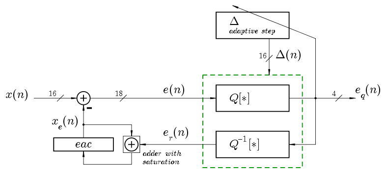
The input <math>x(n)</math> must be 16-bit two's complement audio data. The encoder takes a 16-bit two's complement audio sample and returns a 4-bit sign-magnitude ADPCM code <math>e_q(n)</math>. The encoder's internal state is composed by eac and index registers (inside adaptive step block).
Quantizer and Inverse Quantizer
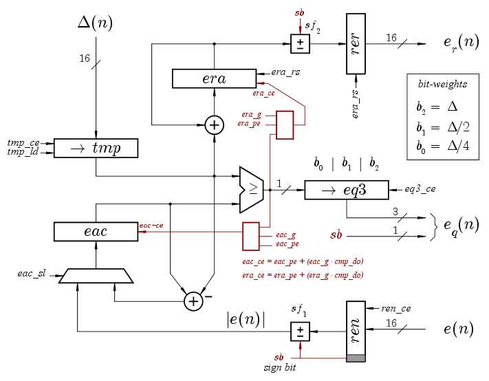
The following figure corresponds to the two blocks inside the green box above: direct and inverse quantizers. This datapath computes, in parallel, the quantized sample <math>e_q(n)</math> and the associated reconstructed sample <math>e_r(n)</math>. The signal <math>e_r(n)</math> is represented with 16 bits two's complement. The residue <math>e_r(n)</math> is represented with 4 bits sign-magnitude:
[sb b2 b1 b0] = (-1)^sb * \Delta * [b2 + b1 * 2^{-1} + b0 * 2^{-2}]
The two NAND/NOR red gates dramatically simplify the control FSM, which is 3-bit counter (8 states). The fsm's graph is simply e0 -> e1 -> e2 -> e3 -> e4 -> e5 -> e6 -> e7

| State | era_g | era_pe | era_rs | ren_ce | rer_ce | tmp_ce | tmp_ld | eac_g | eac_pe | eac_sl | eq3_ce | busy |
|---|---|---|---|---|---|---|---|---|---|---|---|---|
| e0 | 0 | 1 | 1 | 0 | 0 | 0 | - | 0 | 0 | 0 | - | 0 |
| e1 | 0 | 0 | 0 | 1 | 0 | 1 | 1 | 0 | 0 | 0 | 0 | 1 |
| e2 | 0 | 0 | 0 | 0 | 0 | 0 | - | 0 | 1 | 1 | 0 | 1 |
| e3 | 1 | 0 | 0 | 0 | 0 | 1 | 0 | 1 | 0 | 0 | 1 | 1 |
| e4 | 1 | 0 | 0 | 0 | 0 | 1 | 0 | 1 | 0 | 0 | 1 | 1 |
| e5 | 1 | 0 | 0 | 0 | 0 | 1 | 0 | 1 | 0 | 0 | 1 | 1 |
| e6 | 0 | 1 | 0 | 0 | 0 | 0 | - | 0 | 0 | 0 | 0 | 1 |
| e7 | 0 | 0 | 0 | 0 | 1 | 0 | - | 0 | 0 | 0 | 0 | 0 |
Adaptive Quantizer Step
The delta coefficient table uses 1 BRAM whereas the delta index ROM is implemented normally with LUTs by the synthesizer (it's too small, consume a complete BRAM for it would be a wasteful)
