Updated:
VHDL IP: DC97
Block description
| Port | Dir | Type | Description |
|---|---|---|---|
| n_reset | Input | signal | Asynchronous reset, active-low |
| clk | Input | signal | System clock. 27MHz (to use other frequency, change the counter that controls the duration of reset signal) |
| ac97_sdata_o | Output | signal | AC97-Link signal. Outgoing bit stream |
| ac97_sdata_i | Input | signal | AC97-Link signal. Incoming bit stream |
| ac97_sync | Output | signal | AC97-Link signal. Sync |
| ac97_bitclk | Input | signal | AC97-Link signal. Clock generated by AC97 codec |
| ac97_reset | Output | signal | AC97-Link signal. Reset |
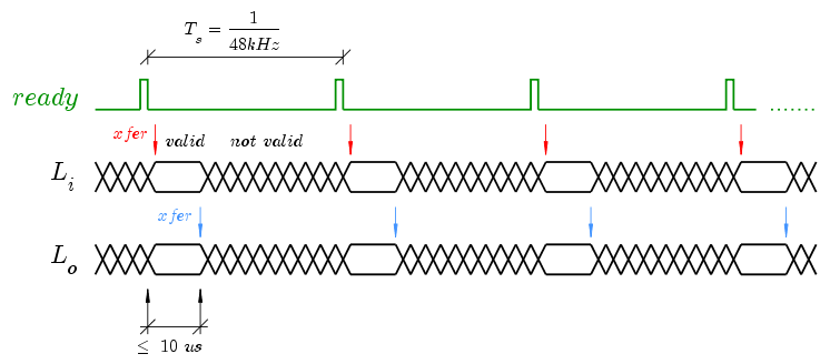
| ready | Output | signal | A one-cycle pulse every (1/48kHz) seconds signaling the start of a new AC97-Link frame, get/put audio data before 10 us elapse |
| L_o | Output | 16-bit bus | 16-bit sample to play, L channel |
| R_o | Output | 16-bit bus | 16-bit sample to play, R channel |
| L_i | Input | 16-bit bus | Recorded 16-bit audio sample, L channel |
| R_i | Input | 16-bit bus | Recorded 16-bit audio sample, R channel |
| cmd_addr | Input | 08-bit bus | Address of a AC97 codec hardware register to be written |
| cmd_data | Input | 16-bit bus | Data to be written in the AC97 hardware register |
This VHDL macro is a simple AC97 audio controller (Digital Controller' 97 (DC97) in the nomenclature used in the
standard document) for play/rec stereo 16-bit 48kHz. It has an extremely simple interface. It doesn't have
neither FIFO queues to store audio samples nor DMA signals but an interrupt mechanism and, therefore, it must be
serviced in real-time. After a ready signal pulse, you have aprox. 10 us to transfer audio data,
if not, the opportunity is lost and you must wait to the next pulse.
- sampling frequency is fixed at 48kHz
- 16-bit resolution
- play/rec stereo (L, R channel)
- this macro in intended to let you do stereo audio experiments moving data in/out with a simple FSM controller (or PicoBlaze) without the burden of a complete SoC bus interface, but, you can implement FIFO queues and, e.g., a Wishbone bus interface on top on this macro if necessary (it's not that difficult).

The AC97 codec has internal hardware registers that store information like volume, gain, record source selection, etc.
Refer to the datasheet of your codec for more information. For example: register 0x1A selects record source (MIC is 0x0000,
LineIn is 0x0404). You can use dc97cmd block (included in source file) which is a simple FSM that periodically sends a
standard configuration data (select input and volume). Connect dc97cmd to dc97
cmd_addr and cmd_data ports.
Synthesis report
| Device | xc3s400-4ft256 |
| Slices | 93(dc97) + 12(dc97cmd) |
| FF | 123 |
| LUTs | 111 |
| IOBs | 96 |
| Global clocks | 2 |
| Maximum clock frequency | 84.764 MHz |
Interface with PicoBlaze
If you want to use PicoBlaze to process audio (and why not?) the recommended way to do this is to use interrupts.
Maintain the ready interrupt signal with a FF like this:
      -- interrupt retainer flip-flop
      process (n_reset, clk)
      begin
      if n_reset = '0' then
      interrupt <= '0';
      elsif rising_edge(clk) then
      if interrupt_ack = '1' then
      interrupt <= '0';
      elsif ready = '1' then
      interrupt <= '1';
      end if;
      end if;
      end process;
The ISR (Interrupt Service Routine) could store each audio sample in a buffer with a capacity of N samples prior to process them. The technique is to maintain two buffers to communicate ISR and main program and interchange its contents when required (after N interrupts).
With PicoBlaze running at 27 MHz and with a sampling frequency of 48 kHz, you have (27M/2)/48000 = 281 instructions per sample. It is not a huge DSP capacity but enough to relay audio samples to HW co-processors or to put them in simple frame formats (multimedia containers like OGG).
Take in mind that, if you plan to do a relatively complex relaying/processing, PicoBlaze will be smaller than the equivalent FSM (Finite State Machine). Do not underestimate the power and compactness (< 100 slices) of PicoBlaze.
Download
- dc97.vhd. This file contains two components: dc97 (the AC97 controller) and dc97cmd (a small FSM to to setup codec's registers). The latter block is not strictly required, you can setup registers by software, for example.